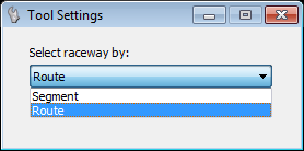
| Select Raceway
|
Click this option to select a raceway in the drawing
to modify its properties. The Tool Settings dialog displays (see above)
prompting you to select the method by which the raceway is selected (Segment or
Route).
|
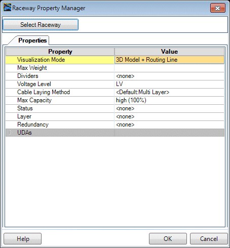
| Visualization Mode
|
Possible Visualization:
- 3D Model - Shows
only the 3D Model
- Routing Line - Shows
only the routing lines
- 3D Model + Routing
Line - Shows both, 3D Model and routing lines
|
| Max Weight
|
Enter the maximum weight possible on selected
raceway system.
|
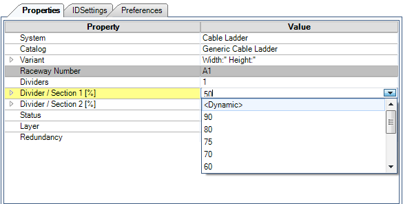
| Dividers
|
Number of dividers:
|
| Divider/Section [%] (OPTIONAL)
|
If the raceway contains dividers, then these fields
display letting you define the percentage of space each divided section will
occupy. A pick list provides commonly used capacity percentages so that you can
quickly set the capacity.
The <Dynamic> option is designed to
automatically calculate the size of the sections created by the divider in
order to allow the maximum number of cables to be routed.
When the <Dynamic> option is chosen the
system will begin routing assuming that the first section has 100% available.
- If it fills up the
entire raceway with cables in this one section then no other cables can be
routed.
- If it fills up 80%
then the remaining 20% can be used for other cables in the second section.
- If it fills up only
20% in Section 1, then Section 2 will automatically be set to 80% even if no
cables need to be routed in that section.
|
| Voltage Level
|
Possible Voltage Level:
|
| Layer
|
Possible Layer:
- <none>
- Layer 1 - Layer 10
|
| Redundancy
|
Possible value:
- <none>
- Redundancy A
- Redundancy B
- Redundancy C
|
| Status
|
Possible value:
- <none>
- Design
- Released
- Built
|
| Max Capacity
|
Possible value:
- <none>
- low (50%)
- medium (75%)
- high (100%)
|
| Accessories (Route)
|
Selection of possible Accessories (Hanger,...)
|
| Accessories (Raceway)
|
Selection of possible Accessories sets (Brackets,
Dividers,...)
|
| Voltage Level <Section 2-4>
|
Possible Voltage Level for additional section:
|
| Layer <Section 2-4>
|
Possible Layer for additional section:
- <none>
- Layer 1 - Layer 10
|
| Redundancy <Section 2-4>
|
Possible value for additional section:
- <none>
- Redundancy A
- Redundancy B
- Redundancy C
|
| Max Capacity <Section 2-4>
|
Possible value for additional section:
- <none>
- low (50%)
- medium (75%)
- high (100%)
|